Impulse 1.0
Baseline Architecture

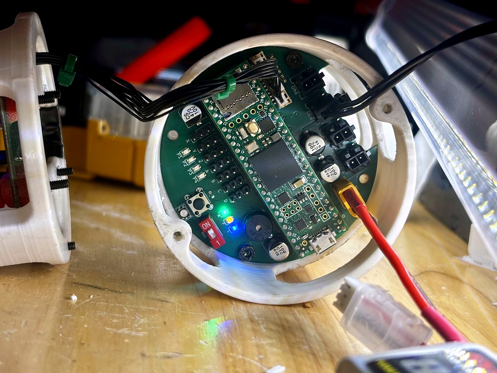
Teensy 4.1 with MPU6050/BMP280 and initial pyro circuitry; pyro path was non-functional.
Sisyphus — Subsystem
Impulse 2.5 is the current custom Sisyphus avionics board for flight sensing, actuator control, pyro events, and telemetry. This layout groups hardware photos, CAD, and specifications into one place for faster understanding.
PCB History
The flight computer went through several major hardware revisions. Each iteration solved problems revealed by the last, from basic pyro failures to full SMD layout and trace-width discovery.
Impulse 1.0
Teensy 4.1 with MPU6050/BMP280 and initial pyro circuitry; pyro path was non-functional.
Impulse 1.1-1.3

Expanded servo outputs and switched to larger MOSFETs, but pyro reliability remained unresolved.
Impulse 1.4

Added dedicated LiPo circuit for pyros to isolate high-current firing from core avionics.
Impulse 2.0

Attempted ESP32-S2 full-SMD board and adopted BNO055 plus DPS310 sensor stack for future revisions. I had no idea what I was doing in hindsight.
Impulse 2.1

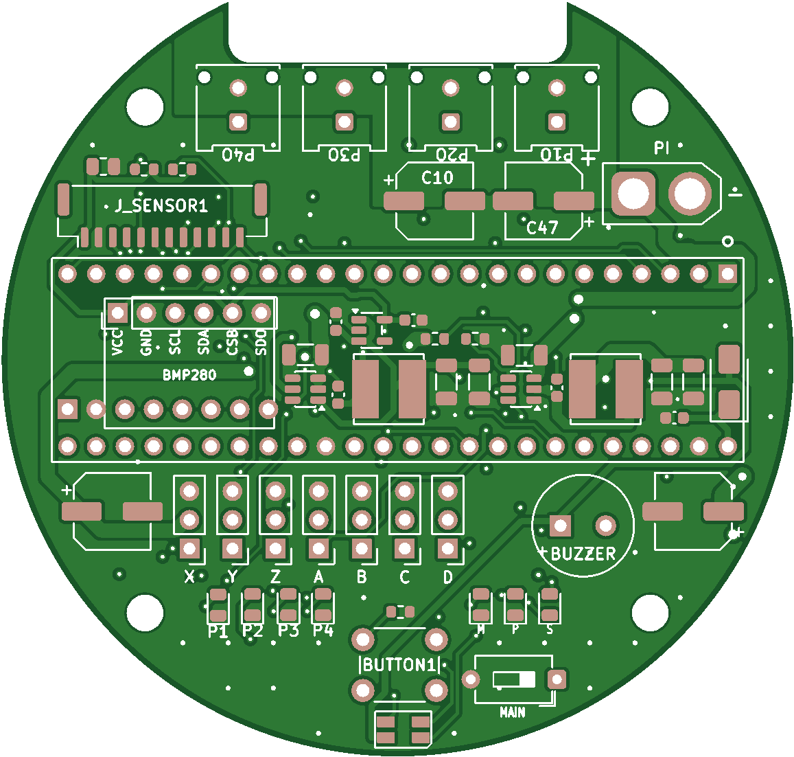
Mostly-SMD layout with Teensy 4.1, continuity checks, and dedicated sensor power; pyro troubleshooting intensified.
Test Boards

Isolated pyro and regulator boards exposed trace-width as the pyro ignition bottleneck.
Impulse 2.2

Widened pyro traces enabled reliable firing and powered the first successful Sisyphus launch.
Impulse 2.3

Swapped to smaller SMD MOSFETs while preserving wide pyro routing for robust ignition.
Impulse 2.4
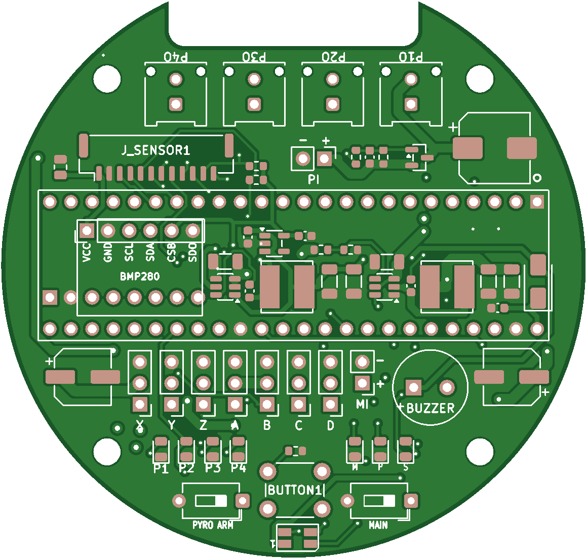
New pyros with MOLEX connections, fully SMD power regulation, seperate sensor board JST connection plus redundant onboard sensors, battery charge and sensor detect LEDs, and 5 additional servo outputs.
Sensor Board
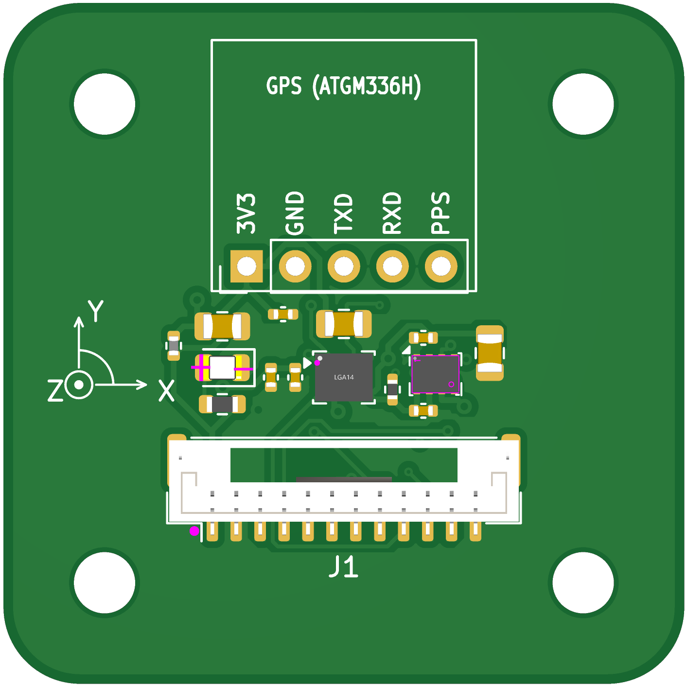
Separate module with an ICM-42688 IMU, DPS-310 barometer, and ATGM336H GPS, mounted on vibration dampers and fused in software by a Kalman-based state estimator.
Impulse 2.5
Switched from two small lipos to one big lipo battery with higher discharge rate for pyros. Bulked pyro FETs to give significant practical margin. Added multi-layer planes for more robust pyro circuit.