Ares — Subsystem

PCB & Flight Electronics

The PCB bridges the gap between the code and the rocket hardware, especially the TVC servos and pyro channels. The hard part was always the same: fit the components onto a board that could actually be wired cleanly, debugged quickly, and trusted in flight.

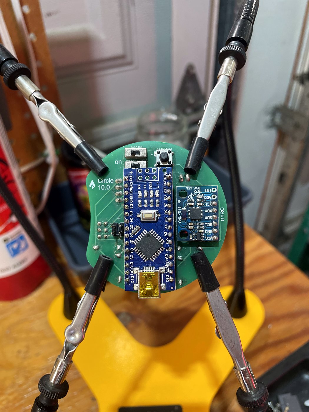
An Ares flight computer board held in helping hands on the bench
An Ares flight computer on the bench, mid-assembly.
Rectangle 1.0 electronics bay mounted in the rocket
Rectangle 1.0 mounted vertically in the original Ares electronics bay.

PCB Specs

  • Purpose: Translate the control code into real actuator and pyro outputs that the rocket can use in flight.
  • Main packaging challenge: Fit sensing, power, switching, and connectors on a compact board with wiring that stayed functional under launch prep pressure.
  • Baseline hardware: Started with an Arduino Nano and MPU-6050 gyro/accelerometer for early TVC stabilization prototypes.
  • Control outputs: Began with 2 servo channels, then expanded to support additional servo and pyro outputs in later revisions.
  • User interface additions: RGB stage LED first, then dedicated toggle switches and a launch button for easier field operation.
  • Development pattern: Every new revision fixed a real launch-day wiring, layout, or troubleshooting bottleneck exposed by the previous board.

Hardware Notes

Development & Iterations

The Ares flight computer evolved quickly from a basic first prototype into a much more usable launch board. Each version fixed a specific packaging, wiring, or field-ops problem that showed up in the previous design.

Rectangle 1.0

First Flight Prototype
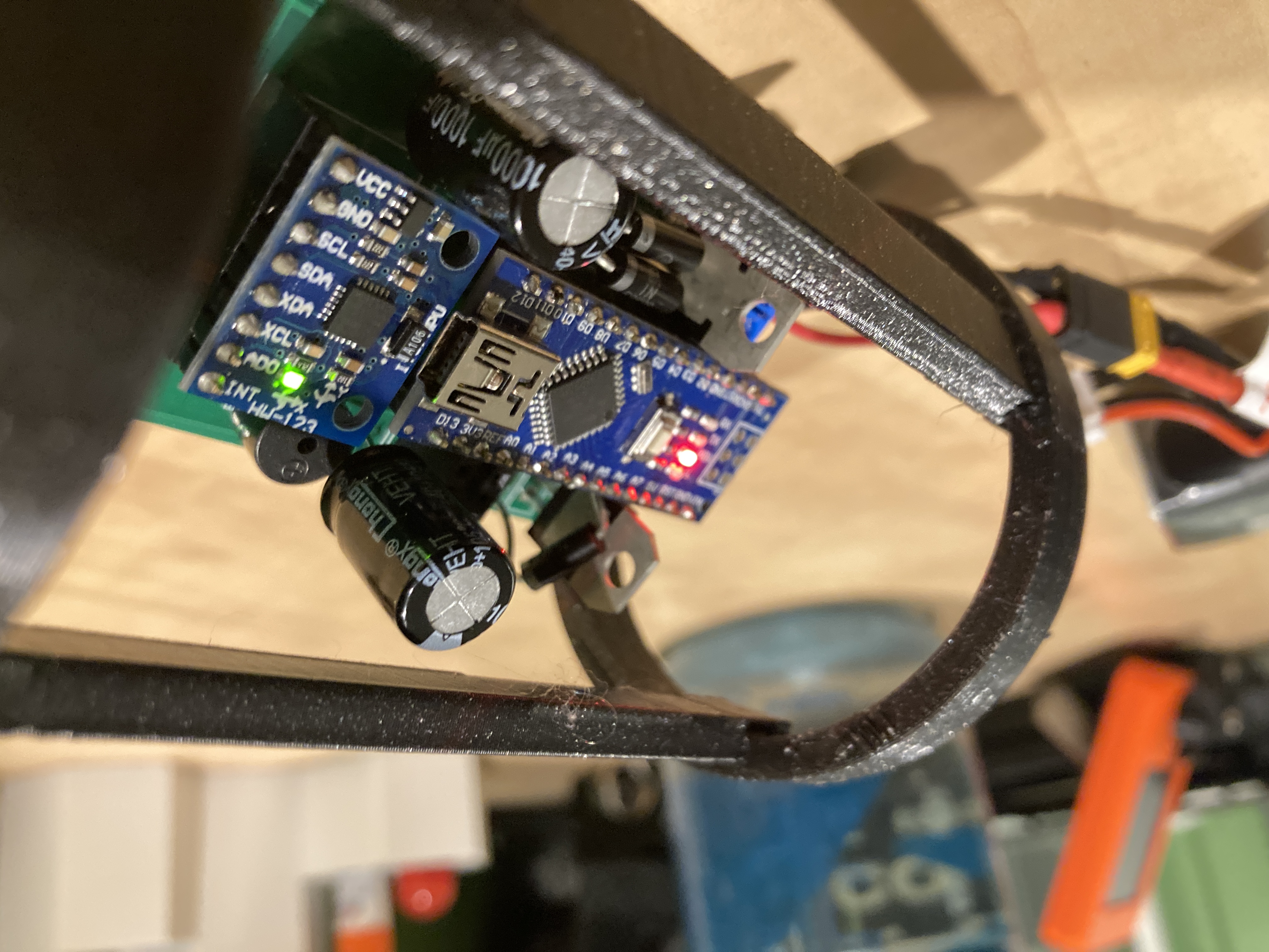
Rectangle 1.0 flight computer board

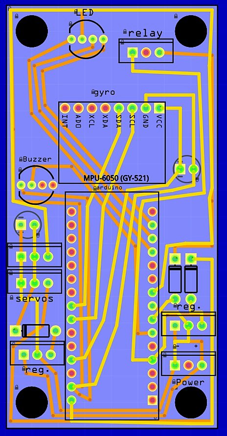
Miles designed this first Ares E-Bay PCB in Fritzing. It used an Arduino Nano, an MPU-6050 gyro/accelerometer, and two servo outputs, just enough to run one TVC. It flew on our first launch and worked well enough for a first prototype.

Circle 5.0

Horizontal Repackage
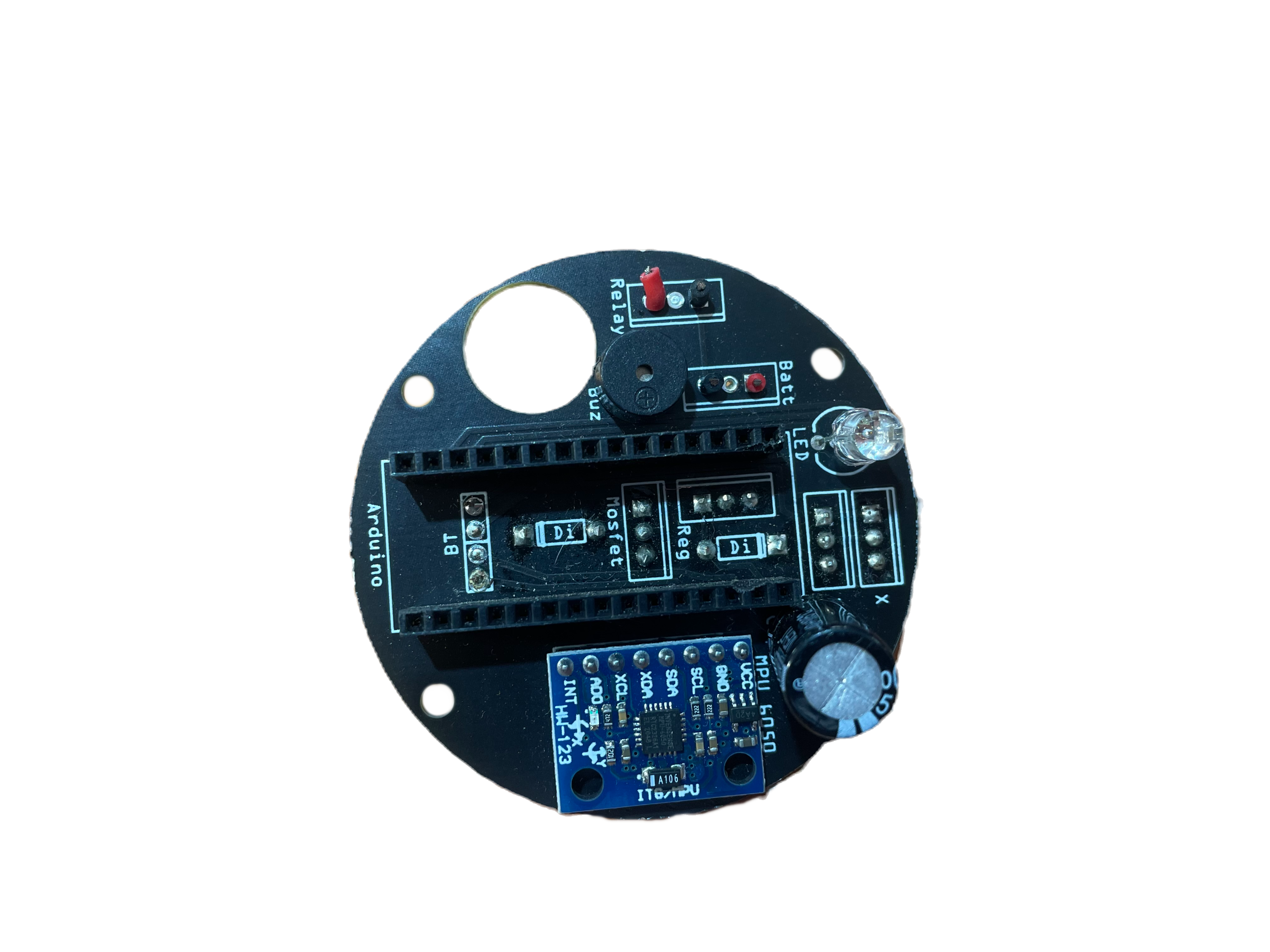
Circle 5.0 PCB layout

After the vertical Rectangle 1.0 layout, we redesigned the board to mount horizontally for easier user interfacing and to try to reduce gyro drift. I also added an RGB LED that changed color by flight stage. This revision still drove two servos, but now included one pyro channel.

Circle 8.0

Wiring Expansion
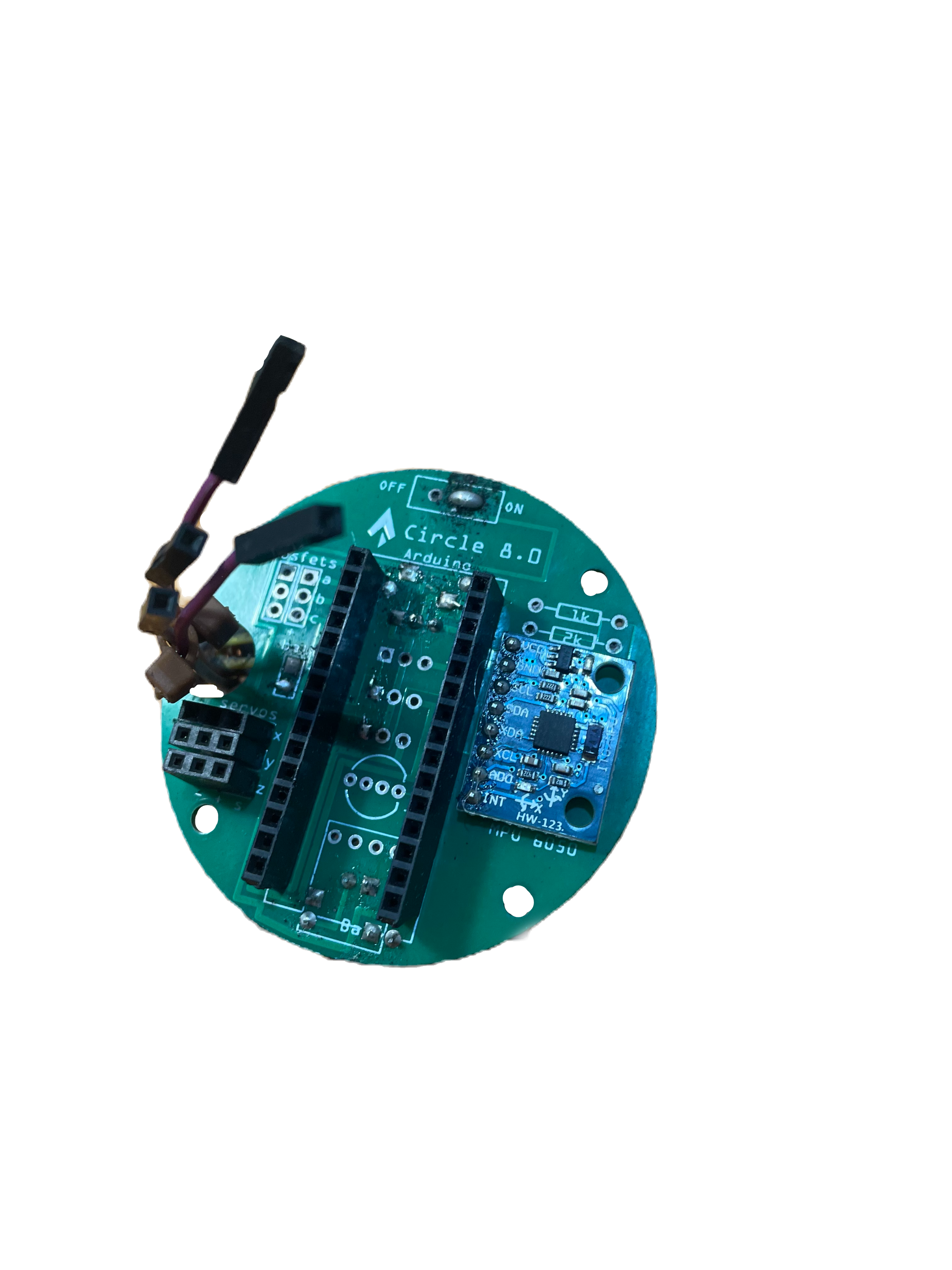
Circle 8.0 PCB layout

We flew this board at the second launch. Building on the earlier circular layout, it optimized spacing and wiring to make room for three servo outputs and three pyro channels, while also fixing a small gyro wiring issue.

Launch-Day Fix

MOSFET Rewire

Circle 8.0 board used during launch-day troubleshooting

The day before launch, the MOSFETs driving the pyro channels were still not working. We eventually realized we had wired them wrong the entire time, so Miles did a sketchy but effective hot-glue-and-jumper-wire rework to get the board flight-ready.

Circle 10.0

Successful Launch Board
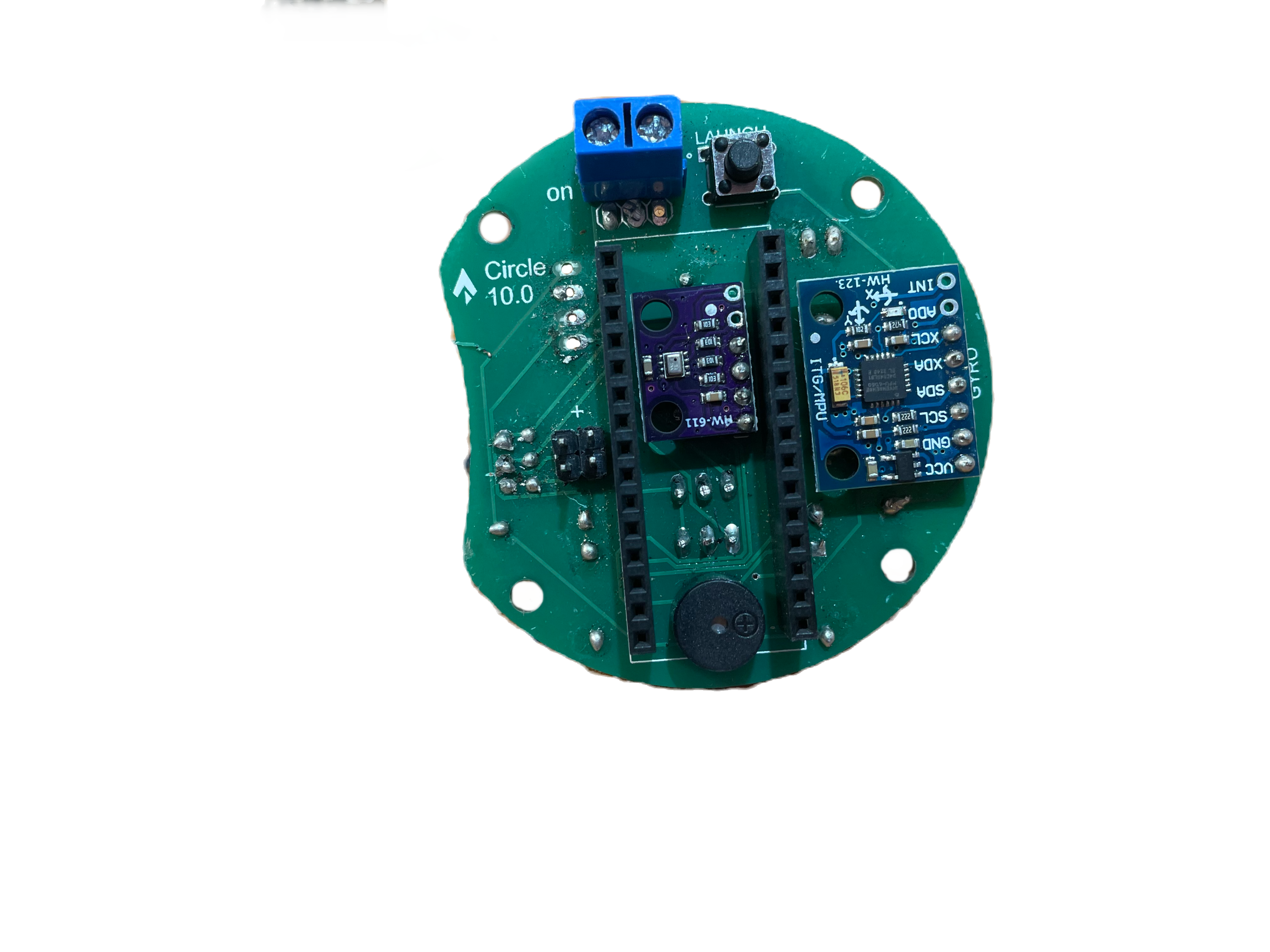
Circle 10.0 PCB layout

This was the board we flew on the successful third launch. It added a BMP-180 barometer, SD-card logging, two pyro channels, two servo channels, plus a main toggle switch, pyro toggle switch, and a launch button that started a 30-second countdown.
← Back to Ares