Ares — Subsystem

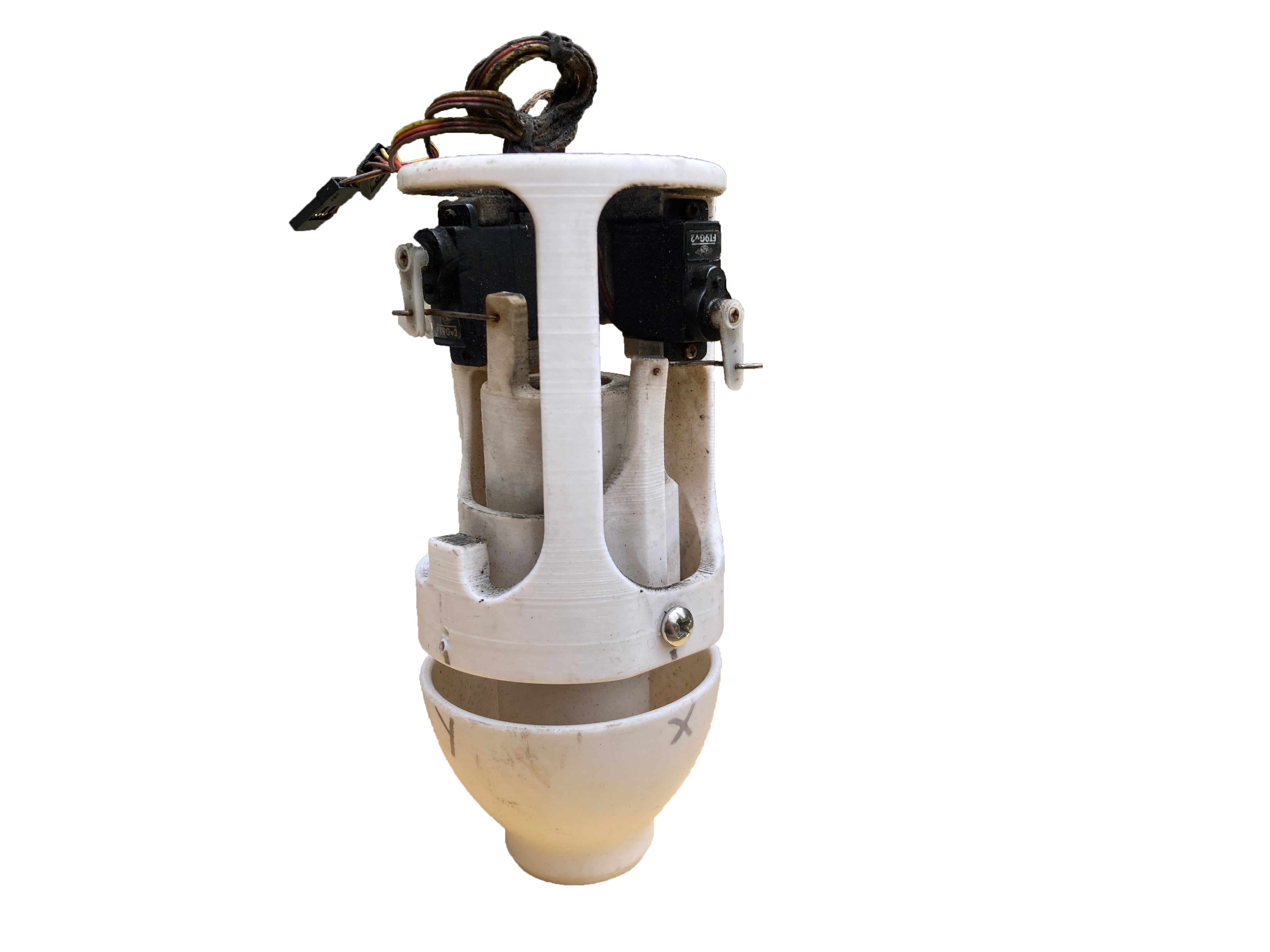
Thrust Vector Control

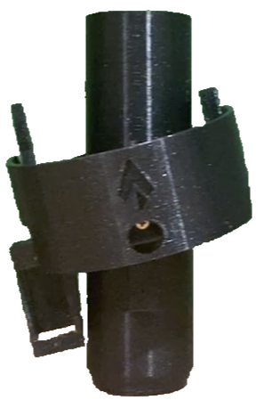
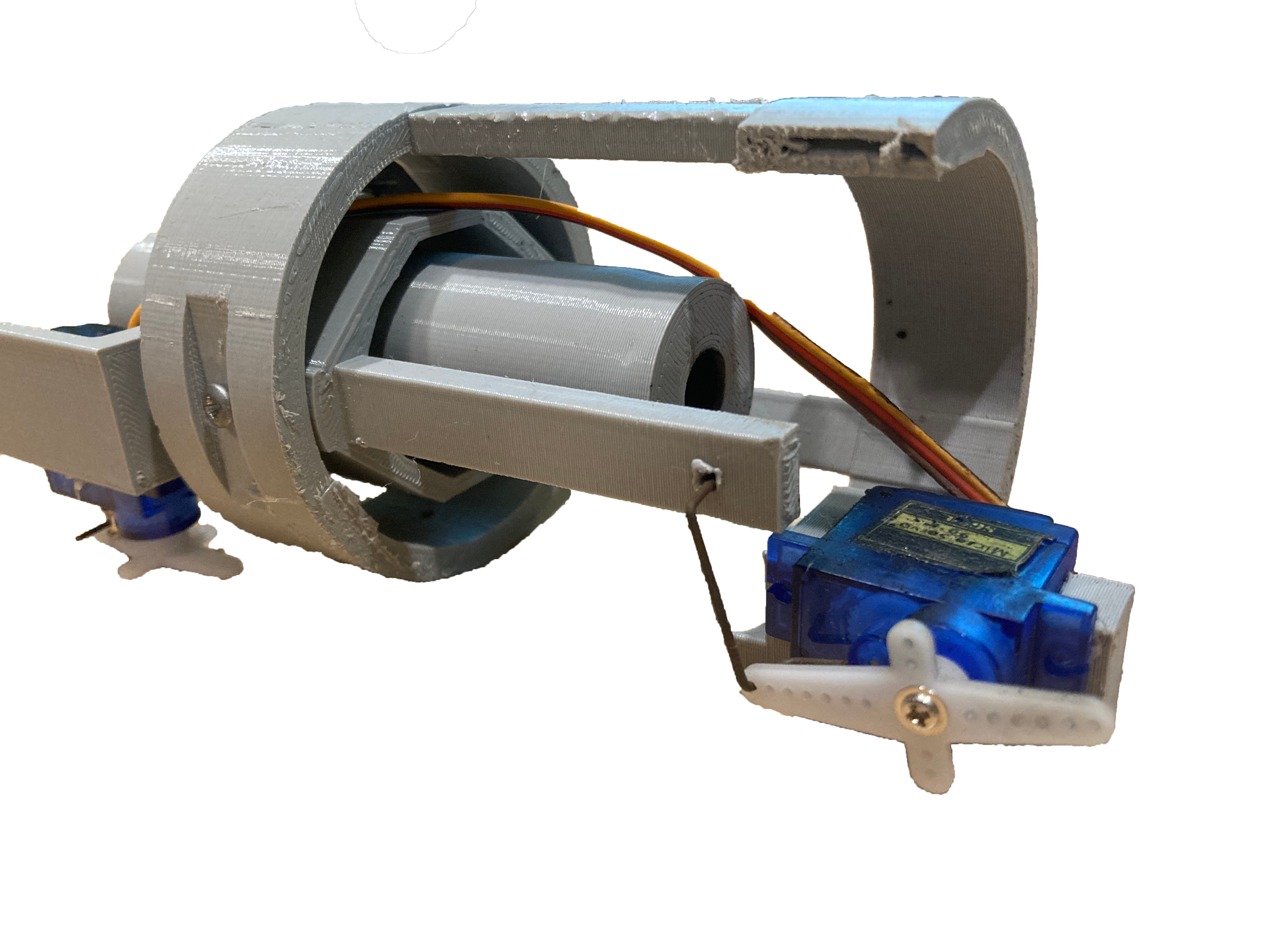
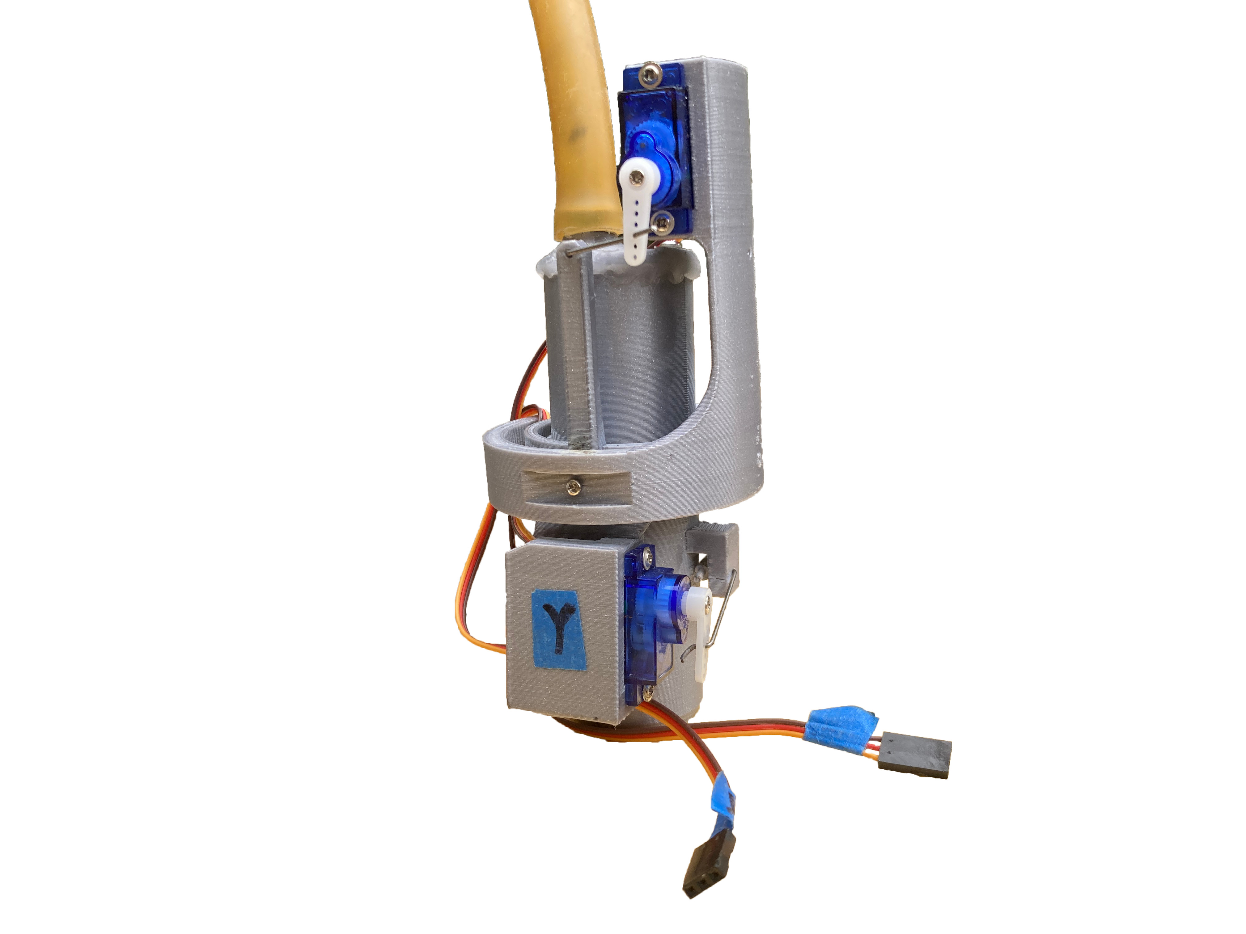
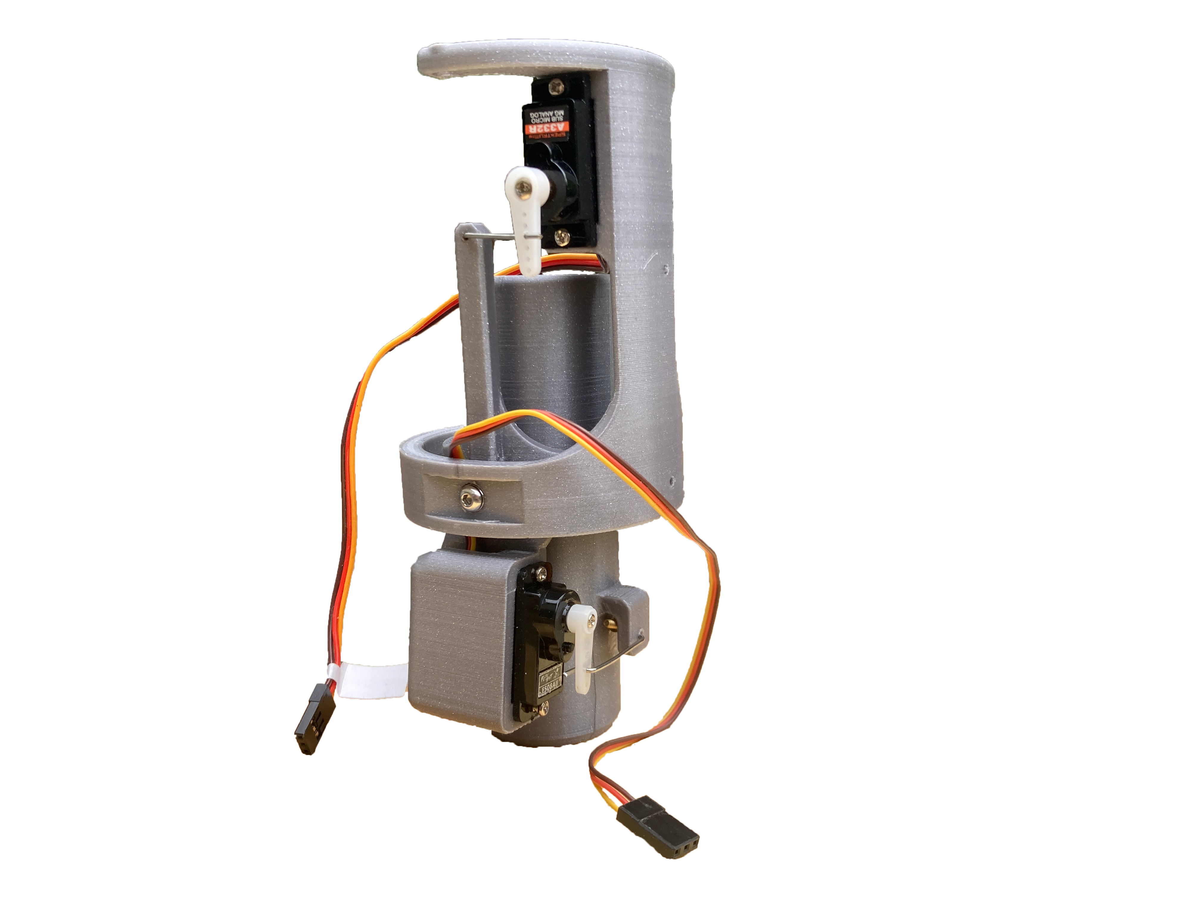
Five iterations of two-axis gimbal mounts driven by dual servo actuators, providing real-time attitude correction during powered ascent. Each revision improved stiffness, reduced mechanical play, and increased servo authority to meet tighter stabilization targets.

Gimbal Geometry Servo Linkage Closed-Loop PD Burnout Analysis

Iteration

A1 TVC

First Ares gimbal design. Established the two-axis servo layout and basic linkage geometry. Identified early issues with mechanical slop and servo overload under motor thrust.

Ares A1 TVC gimbal iteration

Iteration

A2 TVC

Redesigned linkage arms to reduce slop and improve commanded angle fidelity. Adjusted servo horn geometry to better match the required deflection range for attitude correction.

Ares A2 TVC gimbal iteration

Iteration

A3 TVC

Stiffened the gimbal frame and adjusted pivot geometry to reduce flex under motor load. Improved moment arm consistency across the deflection range.

Ares A3 TVC gimbal iteration

Iteration

A4 TVC

Refined servo mounting and gimbal geometry to minimize oscillation at the controller's bandwidth limits. Pre-flight PD gain sweeps showed improved stability margins over A3.

Ares A4 TVC gimbal iteration

Final Ares TVC iteration. Achieved best controlled ascent across flight tests. Static fire confirmed reliable servo authority under full motor thrust. Burnout transition analysis showed phase lag requiring higher-order control for post-thrust flight.

Ares A5 TVC gimbal final iteration
A5 TVC gimbal — final geometry.
← Back to Ares